
1-805-484-2992
Quotes - Engineering - SalesInstallation And Piping
Details that decide the service life
A significant share of the coolers we see failing early were installed in a way that guaranteed it. The selection was sound, the materials were right, and then the unit was piped backwards, mounted where nobody could service it, or connected without a vent so the top row of tubes never saw coolant. None of those faults show up on commissioning day. They show up two years later as a warm engine, a leak, or a bundle that cannot be withdrawn without cutting pipework.
A cooler can be correctly selected and still fail early because of how it was piped. Seawater on the tube side, a vent at the shell high point, and room to pull the bundle are the three that matter most.
The most important single rule is that seawater goes on the tube side. That puts the corrosive fluid inside copper-nickel or titanium tubes where the zinc anodes in the bonnets can protect it, keeps the shell and its internals out of contact with salt water, and lets the seawater passages be cleaned by pulling two bonnets rather than opening the shell. Piped the other way around the same cooler corrodes faster and cannot be maintained without dismantling it.
The second is venting. A horizontal shell fills from the bottom and traps air at the top, and trapped air against the upper tubes removes that surface from service entirely. On an engine circuit the vent is taken from the shell high point back to the expansion tank, so the system self-vents continuously rather than relying on somebody remembering to crack a plug. The third is access, because a cooler you cannot open is a cooler that will not be cleaned.
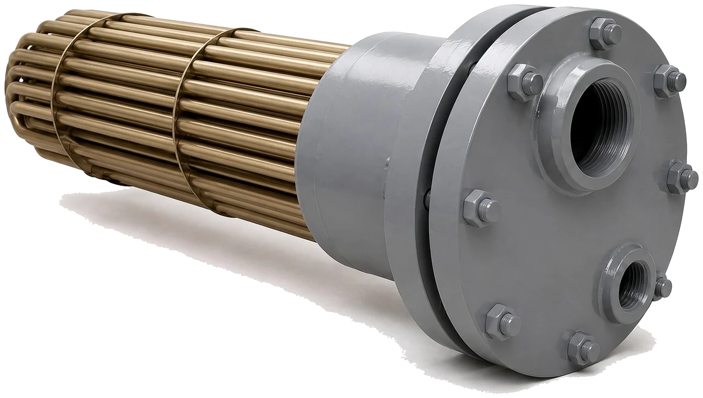
Seawater Inside The Tubes
Every other installation decision can be corrected later; getting the two fluids on the wrong sides is a fault you live with until the cooler fails.
Piping
- Seawater to the bonnet connections
- Coolant or oil to the shell nozzles
- Counterflow arrangement where possible
- Bronze fittings at the cooler
- Isolating valves both sides
Venting
- Vent at the shell high point
- Route the vent to the expansion tank
- Drain at the shell low point
- No air traps in the coolant run
- Vent again after any refill
Mounting
- Support on brackets, not nozzles
- Allow for thermal expansion
- Pull clearance for the bundle
- Access to both anode ports
- Bonnet orientation checked
| MISTAKE | SYMPTOM | CONSEQUENCE | CORRECT PRACTICE |
| Seawater on the shell side | Rapid shell corrosion | Cooler unmaintainable and short lived | Seawater through the tubes always |
| No shell vent | Warm at load, fine at idle | Top tubes idle, surface lost | Vent high point to expansion tank |
| Weight carried on nozzles | Cracked nozzle or weeping joint | Leak into the machinery space | Brackets take the load |
| No pull clearance | Cannot withdraw the bundle | Cooler never gets cleaned | Leave bundle length plus margin |
| Steel fittings at the bonnets | Fitting corrodes, anodes vanish | Galvanic attack at the joint | Bronze fittings or isolating unions |
| No isolating valves | Whole system drained to clean | Cleaning gets postponed | Valve both sides of the cooler |
Which Fluid Goes Where
And why it is not negotiable
Our marine coolers are built with seawater on the tube side: copper-nickel or titanium tubes, zinc anodes in the bonnets, brass or 316 tubesheets. Engine coolant or oil goes on the shell side, where the shell can be steel or 316 because it never touches salt water. That arrangement is what makes the anode protection effective and the seawater passages accessible.
It also determines the pressure design. The tube side is rated to 150 PSI on these frames while the shell side carries 250 to 300 PSI depending on the family, which matches a raw water circuit on the tubes and a coolant or hydraulic oil circuit on the shell. If your duty puts high pressure where the rating is lower, tell us before ordering.
Venting And Draining
Air is a surface thief
Air trapped in the top of a horizontal shell insulates the upper tubes completely, and the resulting loss of surface is easy to mistake for fouling or undersizing. The permanent fix is a vent connection at the shell high point piped back to the expansion tank, so the circuit vents itself every time it is filled or run.
Fit a drain at the low point too. It makes cleaning and layup preparation straightforward, and it lets you flush the shell side without dismantling anything. On seawater side, the ability to drain and fresh water flush before a layup is one of the most useful protections against the stagnation problems covered under Corrosion Control.
Support, Expansion And Vibration
Mechanical loads on a marine mounting
A cooler full of water is heavy, and a vessel provides vibration and hull movement continuously. Carry the weight on the mounting brackets and never through the pipe connections, and support the pipework independently so its own weight and thermal movement do not load the nozzles. A cracked nozzle on a seawater bonnet is a leak in the machinery space.
Allow for thermal expansion in the coolant pipework, particularly on longer runs, and use flexible sections rather than rigid metal-to-metal connections where the cooler is mounted on the engine and the pipework is on the hull. Rigid coupling between two components that move relative to each other will eventually fatigue something.
Common FAQs
The tube side, on every marine cooler we build. That places the corrosive fluid inside copper-nickel or titanium tubes where the bonnet anodes protect it, keeps the shell free of salt water, and lets the seawater passages be cleaned by removing two bonnets. Reversing it shortens the life and makes routine cleaning impossible.
Yes. A horizontal shell fills from the bottom and traps air at the top, and trapped air against the upper tubes takes that surface out of service completely. The result reads exactly like a fouled or undersized cooler. Pipe a vent from the shell high point back to the expansion tank so the circuit self-vents.
Enough at one end to withdraw the bundle its full length, plus working room to handle it, and enough at both ends to unbolt the bonnets and reach both anode ports. A cooler you cannot open will not be cleaned on schedule, and an anode you cannot reach is an anode that stays in place too long.
We would not. A small steel fitting bolted to a large bronze and copper-nickel cooler is a concentrated galvanic anode and will corrode quickly while consuming your zincs. Use bronze fittings at the cooler, or an isolating union with no bonding wire bypassing it if a material transition is unavoidable.
Three things: pressure gauge points either side of the cooler on the seawater line, a thermometer pocket in the seawater outlet, and isolating valves so the cooler can be opened without draining the raw water system. Together they turn a warm engine investigation from guesswork into a set of readings.
Pipe them in opposite directions where the connections allow it. With seawater entering at the end where the coolant leaves, the temperature difference across the tube wall stays usable along the whole bundle, and the same frame delivers more heat transfer than it would with both fluids running the same way. On a replacement that means checking which bonnet the old seawater inlet hose went to rather than connecting whatever is nearest.
Related

APPLICATIONS • ENGINE COOLING
Jacket Water Cooling
Raw water coolers for engine jacket water, sized by rating.
+ Learn More
ENGINEERING • SELECTION
Flow and Drop
Working inside the pressure your installed pumps can spare
+ Learn More
HEAT EXCHANGERS • PARTS
Zinc Anodes
Anode ports and the access they need at installation
+ Learn More
