
1-805-484-2992
Quotes - Engineering - SalesFlow And Pressure Drop
The constraint the pumps impose
Half of a cooler selection is thermal and half of it is hydraulic, and the hydraulic half is where marine work diverges from industrial practice. In a new plant you choose the pump to suit the exchanger. On a vessel the raw water pump is engine-driven or already bolted to a bulkhead, the coolant pump is part of the engine, and neither is up for negotiation. So the pressure drop the cooler is allowed to develop is fixed before the selection begins, and the frame has to live inside it.
Pass count is the lever that connects the two halves. Adding passes raises tube velocity, which raises the heat transfer coefficient and lets a smaller frame do the same duty. It also raises pressure drop roughly with the square of velocity, and it raises the erosion risk on copper-nickel tubes. So the smallest and cheapest frame that satisfies the heat duty is frequently the one the seawater pump cannot feed and the one that will erode its inlet tube ends in a couple of seasons.
The shell side has its own version of the same problem, and on oil coolers it dominates. Oil viscosity at operating temperature drives both the film coefficient and the shell-side pressure drop, and a cold start makes both far worse. A lube oil cooler sized on hot viscosity alone can develop enough cold drop to lift a relief valve and bypass the cooler entirely, which is exactly when the oil most needs cooling later in the cycle.
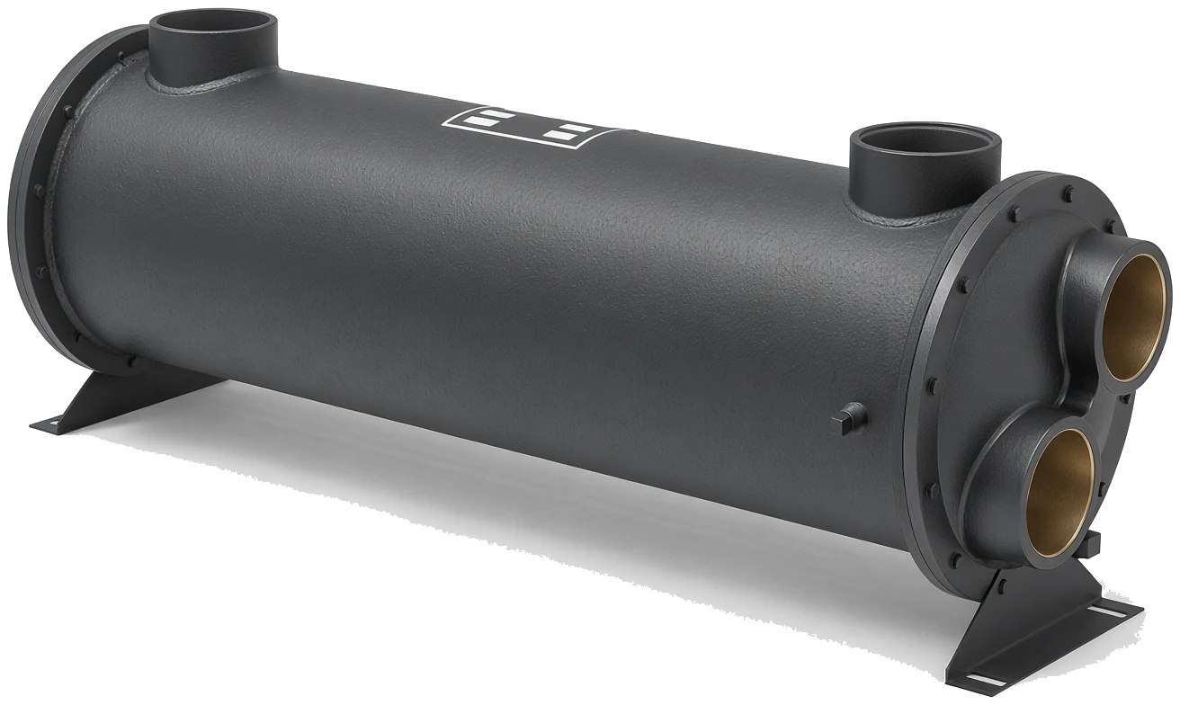
The Pump Decides
You can always find a smaller cooler that meets the heat duty; what you cannot do is make the installed pump push water through it.
Tube Side
- Seawater flow at working speed
- Pass count and free flow area
- Resulting tube velocity
- Drop across bonnets and turns
- Max tube side 150 PSI on our frames
Shell Side
- Coolant or oil flow rate
- Baffle spacing and shell diameter
- Fluid viscosity at temperature
- Cold start viscosity case
- Max shell 250 to 300 PSI by frame
Trade Offs
- More passes, smaller frame, higher drop
- Fewer passes, larger frame, gentler
- Higher velocity risks erosion
- Lower velocity risks fouling
- Cold oil case can dominate sizing
| CHANGE | EFFECT ON SIZE | EFFECT ON DROP | SIDE EFFECT |
| Double the pass count | Smaller frame possible | Rises sharply | Erosion risk on copper-nickel |
| Halve the pass count | Larger frame needed | Falls sharply | Fouling risk if velocity too low |
| Longer tubes, same diameter | More surface per frame | Rises with length | May not fit the space |
| Larger shell, same length | More surface | Falls on both sides | Costs more, needs more room |
| Colder oil at start up | No change | Rises steeply | Relief valve may bypass cooler |
Working Out The Real Seawater Flow
Nominal figures are usually optimistic
The flow that matters is the flow at the vessel's normal working condition, not the pump's catalog rating. An engine-driven raw water pump delivers in proportion to engine speed, so a boat that spends its life at reduced revs has less seawater flow than the nameplate suggests, while a boat run at full throttle may have considerably more than the original selection assumed.
Then subtract the system. A partly blocked strainer, a marginal seacock, long runs of undersized hose and a worn impeller all reduce delivery, and all of them get worse with time. Where we can, we prefer a measured flow or a pump model and speed over an assumed number, because it is the difference between a selection and an estimate.
Why Drop Rises With The Square
The arithmetic behind the trade
Friction loss through a tube rises approximately with the square of velocity, so doubling velocity by doubling the passes multiplies the tube-side drop by roughly four, and the losses through the bonnet turns rise as well. The heat transfer coefficient, by contrast, improves at a much slower rate, so the return on adding passes diminishes quickly while the cost in pressure does not.
That asymmetry is why a marine selection usually settles at a moderate pass count rather than the maximum. It also aligns neatly with the erosion limit on copper-nickel, since both constraints push in the same direction. The velocity page covers the corrosion side of the same decision.
Oil Side Pressure Drop
Viscosity, cold starts and relief valves
Oil coolers are pressure drop problems as much as heat transfer problems. Viscosity at operating temperature sets the shell-side drop, and viscosity at ambient on a cold morning can be many times higher. A cooler that shows a comfortable drop hot can be almost blocked cold, and on a system with a bypass relief valve that means the oil takes the bypass until it warms.
That is sometimes acceptable and sometimes not, and it should be a decision rather than a surprise. Send the oil grade, the flow, the operating temperature range and the relief valve setting, and we will check both the hot and cold cases. See lube oil cooling for how these circuits are usually arranged.
Questions from the yard
Whatever your installed pumps can spare at the required flow, which is the only figure that means anything on a real vessel. Send the pump model or a measured delivery and the flow you need, and we will pick a frame and pass arrangement that fits inside it rather than quote a generic allowance.
Passes raise tube velocity, which improves heat transfer and lets a smaller frame do the duty. But pressure drop rises with roughly the square of velocity while the heat transfer gain is much slower, and high velocity also erodes copper-nickel tubes. So the cheapest frame on paper is often the wrong buy.
That is classic cold viscosity behavior. Oil many times thicker than at operating temperature produces a much higher shell-side drop, and if there is a bypass relief valve in the circuit the oil will take the bypass until it warms through. Tell us the relief setting and we will check both cases at selection.
Give us the pump make and model and the drive speed and we will work from that, or measure the delivery into a bucket over a timed interval if the discharge is accessible. An assumed nameplate figure is the weakest input, because strainers, hose runs and worn impellers all reduce real delivery.
Related

APPLICATIONS • OIL COOLING
Reduction Gears
Gearbox oil circuits and the drop they can tolerate
+ Learn More
ENGINEERING • SERVICE
Installation
Piping, venting and support that protect the selection
+ Learn More
APPLICATIONS • JACKET WATER
HC Series
Frames with NPT or SAE connections accross a wide duty range
+ Learn More
